
تتعلق المشاكل الأساسية المتعلقة بخلط السوائل وتحريكها بميكانيكا تيارات السوائل والوسائل التي يتم بها تحريكها.
مُحرَّك. يتم الخلط بنقل المواد عبر نقل الزخم والاضطراب. التحريك هو نتيجة حركة السوائل المضطربة. في معظم عمليات الخلط واسعة النطاق، يُستخدم دافع دوار لإنتاج تدفق السائل. يمكن توليد الاضطراب بأربع طرق: بتأثير ريشة الدافع على السائل؛ أو باحتكاك السائل بجدران الخزان؛ أو بمرور السائل حول عائق؛ أو بتيارات عالية السرعة تتحرك بجوار تيارات منخفضة السرعة. تتضمن هذه الآلية الأخيرة انقطاعًا في سرعة التدفق، وتلعب الدور الأكبر في خلق الاضطراب والتحريك بواسطة الخلاطات ذات المروحة والتوربينات.
يجب أن يكون خزان الخلط أسطوانيًا بمحور عمودي، وقد يكون قاعه مسطحًا أو مقعرًا أو مخروطيًا ضحلًا. يُنصح بأن يكون عمق السائل مساويًا لقطر الخزان، ولكن يمكن أن يصل عمقه إلى قطرين. في الخزانات الكبيرة، قد يكون عمق السائل أقل، ولكن لا يمكن الحصول على خلط جيد إذا كان العمق منخفضًا جدًا. يجب تجنب الخزانات المربعة أو المستطيلة نظرًا لصعوبة ضمان حركة كافية للسائل في الزوايا.
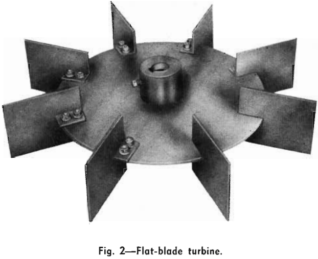
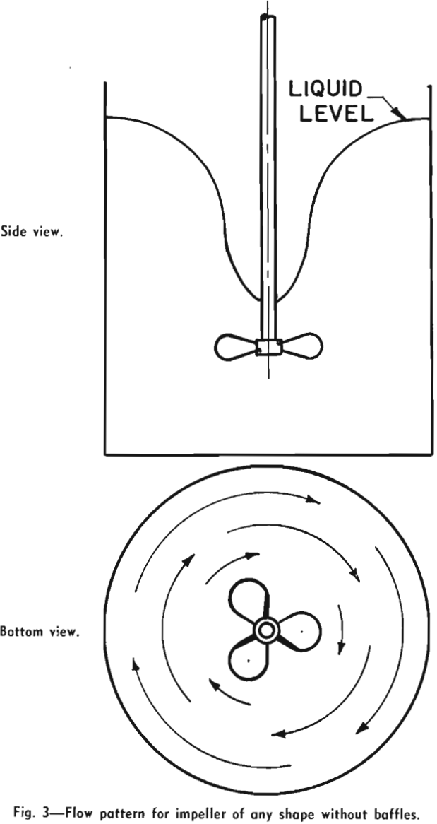
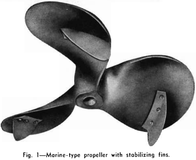
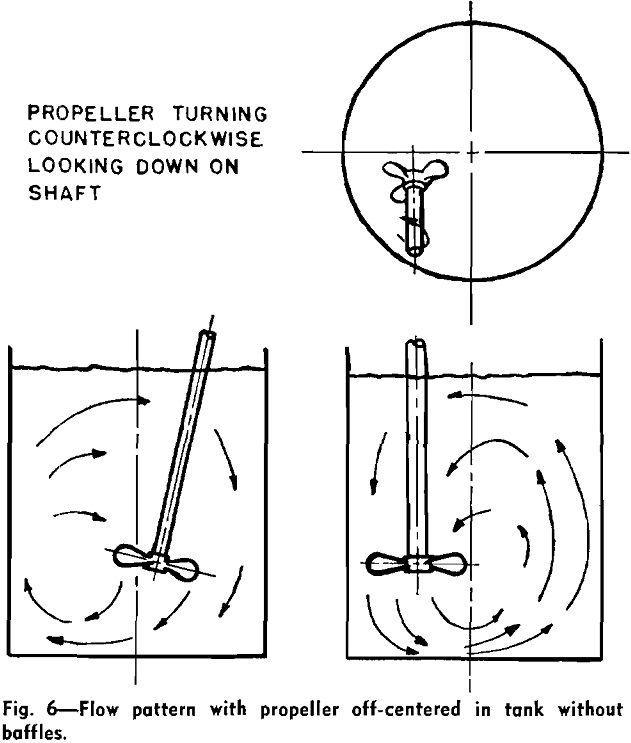
The impeller causes fluid motion and generates, together with the wall, the principal lines of flow through the liquid. When a single impeller of any shape or size is rotated on the center line of a smooth-wall cylindrical tank, the flow motion which is set up is a rotary swirling or vortex motion. The flow is circular and there is practically no vertical motion. The liquid moves as in a merry-go-round, and there is little chance for mixing because liquid is not forced sideways or vertically. If, however, there are obstructions on the wall of the tank or elsewhere, different impellers will give either of two different principal types of flow patterns. The marine-type propeller produces axial flow: the flow leaves the impeller in the direction of the axis of rotation. The flow pattern is illustrated in Fig. 4. It should be noted that there are vertical and lateral-flow lines: liquid is moved up, down, and horizontally, providing good top-to-bottom turnover, and this motion is conducive to good mixing. Note that propellers are almost always operated to discharge downward, and, when two are used on one shaft, they both discharge downward.
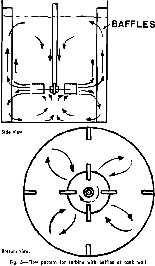
When flat paddles or turbines are rotated with obstruction in the liquid, the liquid moves from the turbines in a plane perpendicular to the axis of rotation. Such motion has been called radial motion, and any impeller which generates this type of flow is classed as a radial-flow impeller.
Ordinarily, impeller shafts enter through the top surface of the liquid, centered, and baffles are used. However, propellers can be used to give axial flow, top-entering without baffles, or side-entering without baffles, in off-centered positions.
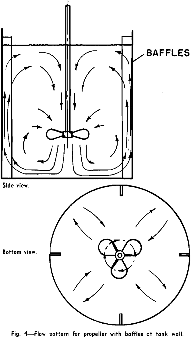
The first consideration for mixing in a process is the choice of the flow pattern best suited to the operation. If solids are to be suspended, vertical flow currents must be developed to oppose the settling velocity of the particles, as in Figs. 4, 5, and 6. Turbines and paddles are effective at low rotational speeds and are preferred for large tanks, since they permit the use of long shafts without submerged bottom bearings.
The power requirements for mixing depend upon the flow pattern desired, the velocities of flow which must be obtained at particular parts of the liquid, and the turbulent energy required. The velocity of flow is dependent upon the quantity of material in motion and the area through which it moves. Thus, a large quantity of flow produced by a small-diameter propeller will result in high velocities over small areas. Such flow will produce high intensity turbulence, but the scale of the turbulence may be low. On the other hand, low velocities of flow may be produced by a large-quantity flow produced by a large-diameter impeller.
Data are available for the flow produced in baffled tanks by square-pitch three-blade
marine-type propellers manufactured by Mixing Equipment Co., Inc.,
Q = K N D³…………………………………………………………………(1)
حيث Q هو التدفق بالقدم المكعب في الثانية، وN هو rps، وD هو قطر المروحة (قدم)، وثابت الماء K هو 0.4. توضح المعادلة أن التدفق يتغير طرديًا مع سرعة المروحة، ومع مكعب القطر. إذا تضاعف حجم المروحة مع ثبات السرعة، فسيزداد التدفق ثماني مرات.
يمكن استخدام المعادلة 1 للتدفق في الخزانات المعطلة من التوربينات ذات الشفرات المسطحة، والمراوح ذات الأشكال الأخرى، باستخدام قيمة مناسبة للثابت K. قيمة K لتوربين بست شفرات مسطحة، مثل الموضح في الشكل 2، هي 0.5.
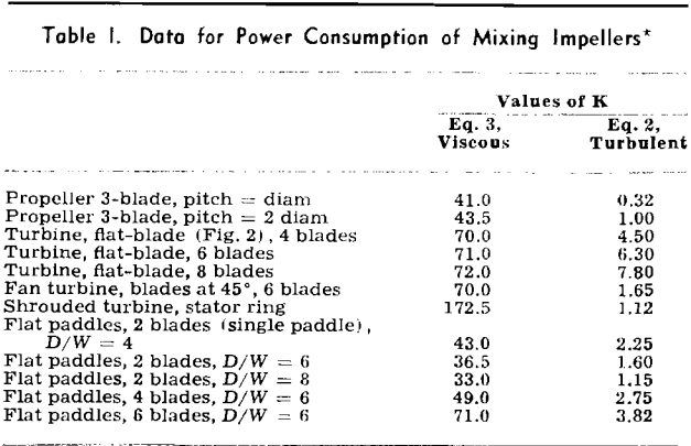
الطاقة المطلوبة لتشغيل المكرهاتإن القوة المطلوبة لتحريك المكره الدوار هي دالة على شكلها وحجمها (D) وسرعتها (N) وموقعها، وخصائص السائل (الكثافة p واللزوجة µ)، وتجهيزات الخزان وتكوينه.
عندما تكون قيمة (D²Np/µ)، وهو عدد رينولدز، أكبر من 5000، ولا يدور سطح السائل في دوامة بل يتدفق، يمكن افتراض أن حركة السائل مضطربة تمامًا. في هذه الظروف، يمكن حساب القدرة بواسطة
P = K/gc p N³ D5………………………………………………………….(2)
حيث P هي القدرة بوحدة قدم-رطل في الثانية، وgc ثابت الجاذبية، وK ثابت (انظر الجدول 1). توضح المعادلة أنه في ظروف التشويش، إذا تضاعفت سرعة أي دافع، فإن القدرة اللازمة لتدويره ستزداد (2³)، أي ثمانية أضعاف. كذلك، إذا كان دافع مماثل في الأبعاد ضعف حجم دافع أصغر، فسيحتاج إلى (2³)، أي 32 ضعف القدرة لتدويره بنفس سرعة الدافع الأصغر.
في الظروف اللزوجة، عندما يكون رقم رينولدز أقل من 10،

تؤدي القوة المفروضة بواسطة المكره إلى تدفق ضد الرأس الكلي
P = Q p H……………………………………………………………………………………[4]
حيث H هو إجمالي الضغط (بالقدم)، ويشمل جميع الضغط الساكن، والضغط، والسرعة، والضغط المضطرب. يتناسب الاضطراب الابتدائي في تيار من دافع طردي مع H؛ وبالتالي، يمكن تطبيق نفس مقدار الطاقة لإنتاج تدفق كبير وضغط صغير (أو اضطراب)، أو تدفق صغير بضغط كبير (أو اضطراب).
على سبيل المثال، مروحة ذات حجم معين تعمل بسرعة 420 دورة في الدقيقة تُنتج وحدة تدفق واحدة عند وحدة ضغط واحدة. إذا شُغّلت مروحة كبيرة، قطرها 1.52 ضعف قطر المروحة الأولى، فيجب أن تدور بسرعة 210 دورة في الدقيقة لإنتاج نفس القدرة. سيؤدي هذا إلى زيادة في التدفق بنسبة 74% (Q = 1.74) وانخفاض في الضغط بنسبة 58% من تلك الموجودة في المروحة الأصغر. يمكن استنتاج هذه العلاقات من المعادلة 2، مما ينتج عنه:
عدد = د -5/3 ………………………………………………………………………………………………………….3/3
حيث يشير الرمز r إلى نسبة الحجم الكبير إلى الحجم الصغير. تُشكل هذه العلاقات أساس اختيار معدات الخلط والتحريك المناسبة، ولتوسيع نطاق النتائج التجريبية لتشمل معدات كبيرة الحجم.

( إبداعي )